Introduction
You need three kinds of connections to get brain signals from an EEG cap into the OpenBCI GUI: a ground, a reference, and one cable per recording electrode. This guide walks through each one in order, assuming no prior experience.
It is written for an OpenBCI Cyton board with the Daisy module stacked on top (16 channels) and a gel EEG cap that has built-in GND and REF locations. Every connection is made with the same kind of adapter cable, called an HPTA cable.
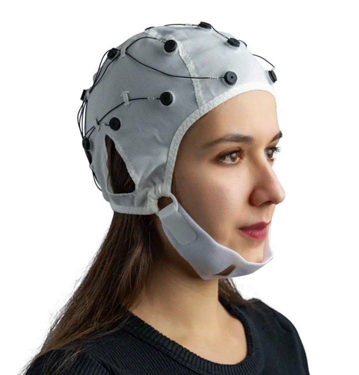
The gel electrode cap. Each black disc is an electrode; gel goes through the small hole in its centre. The chin strap keeps the cap snug so electrodes stay in contact.
Set aside about 15 minutes the first time. Keep the board switched OFF while you connect cables.
Key terms in plain language
| Term | What it means |
| Cyton board | The main board. It amplifies the tiny signals from the cap and handles GUI channels 1–8. |
| Daisy module | An add-on board stacked on top of the Cyton. It adds GUI channels 9–16. |
| Electrode | One metal sensor in the cap that touches the scalp through gel. |
| Channel | One line of signal in the GUI. Each recording electrode becomes one channel. |
| GND (ground) | A spot on the cap that helps cancel out electrical noise shared by the whole body. |
| BIAS | The pin on the Cyton that drives the ground. It connects to the cap’s GND. |
| REF (reference) | The spot on the cap every other electrode is compared against. EEG always measures a difference between two points. |
| SRB | The pin on each board that connects to the reference. |
| N1P–N8P | The eight recording pins on each board, numbered 1 to 8. |
| HPTA cable | A short adapter cable. One end slides onto a board pin, the other plugs into a cap electrode’s lead. |
| Y-splitter cable | A cable with two ends on one side and one end on the other. It joins two pins into a single connection. |
| Ganged together | Joined, so they act as one connection. |
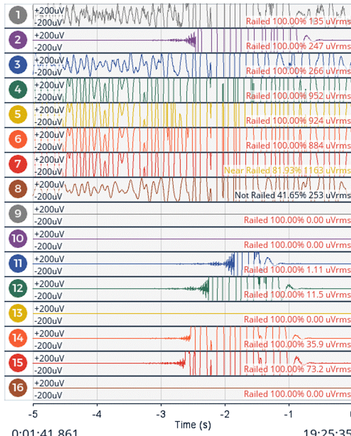
What channels look like in the GUI. Each numbered row is one channel, showing the signal from one electrode over the last 5 seconds. The label on the right of each row shows its status.
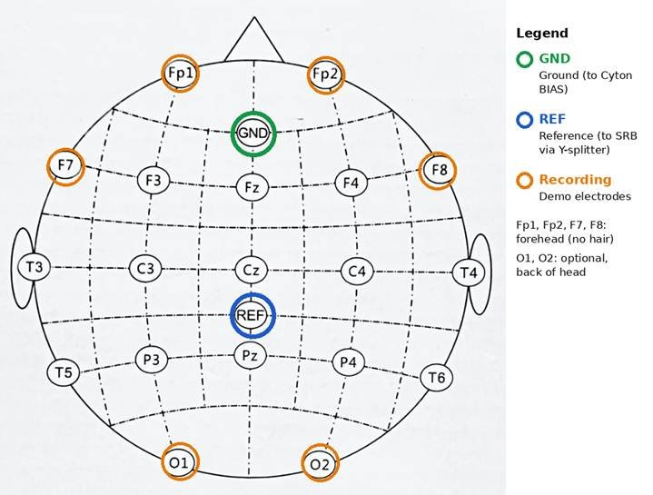
The cap’s electrode map, seen from above with the nose at the top. Green: GND, on the forehead, connects to the Cyton’s BIAS pin. Blue: REF, near the top of the head, connects to the SRB pins via the Y-splitter. Orange: the recording electrodes used in the demo (Fp1, Fp2, F7, F8, plus optional O1 and O2).
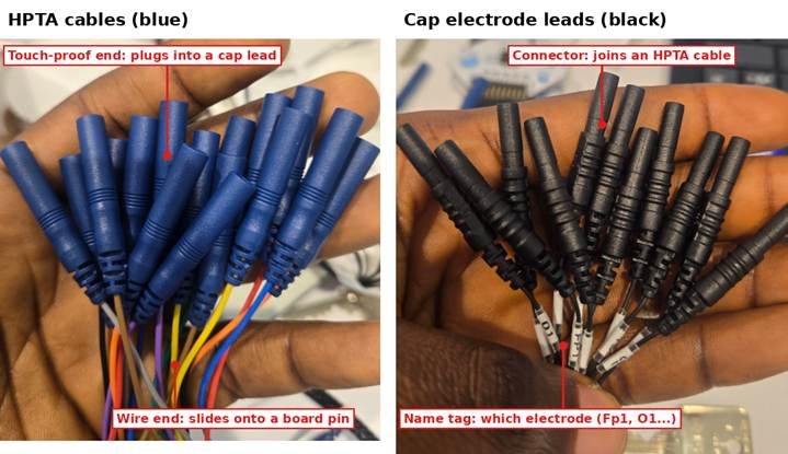
Left: the HPTA cables. Each blue touch-proof end plugs into a cap lead, and the coloured wire end slides onto a board pin. Right: the cap’s electrode leads. Each has a white name tag (such as Fp1 or O1) showing which electrode it comes from. To connect an electrode, join its black lead to a blue HPTA cable, then put that cable’s wire end on the chosen pin.
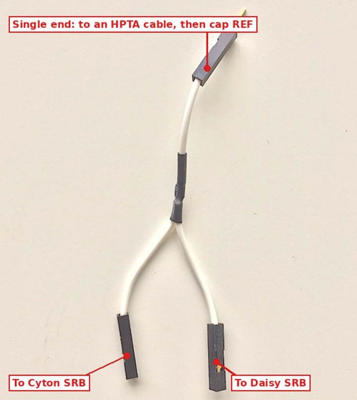
The Y-splitter cable. The two split ends slide onto the bottom SRB pins of the Cyton and the Daisy. The single end joins an HPTA cable, which plugs into the cap’s REF lead.
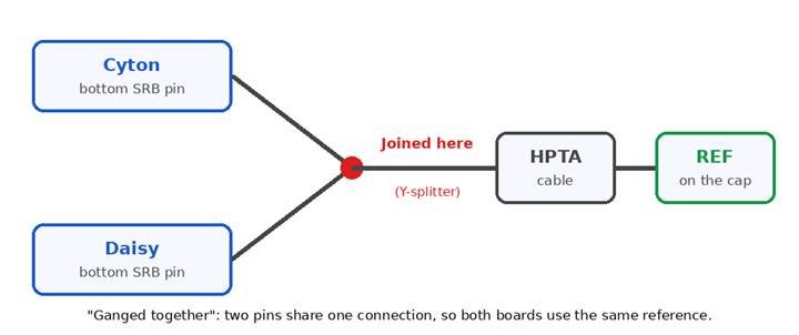
What “ganged together” means. The two SRB pins are joined at the Y-splitter, so both boards share one connection to REF.
What you need
Gather these before you start:
- ☐ Cyton board with the Daisy module stacked on top
- ☐ EEG cap with GND and REF locations
- ☐ One Y-splitter cable
- ☐ HPTA cables: 2 for GND and REF, plus 1 per recording electrode (for example, 6 in total for 4 electrodes)
- ☐ Charged battery for the Cyton, with the board switched OFF
- ☐ USB dongle plugged into the computer, switch set to GPIO6
- ☐ A pen and paper, or this doc, to record your channel map
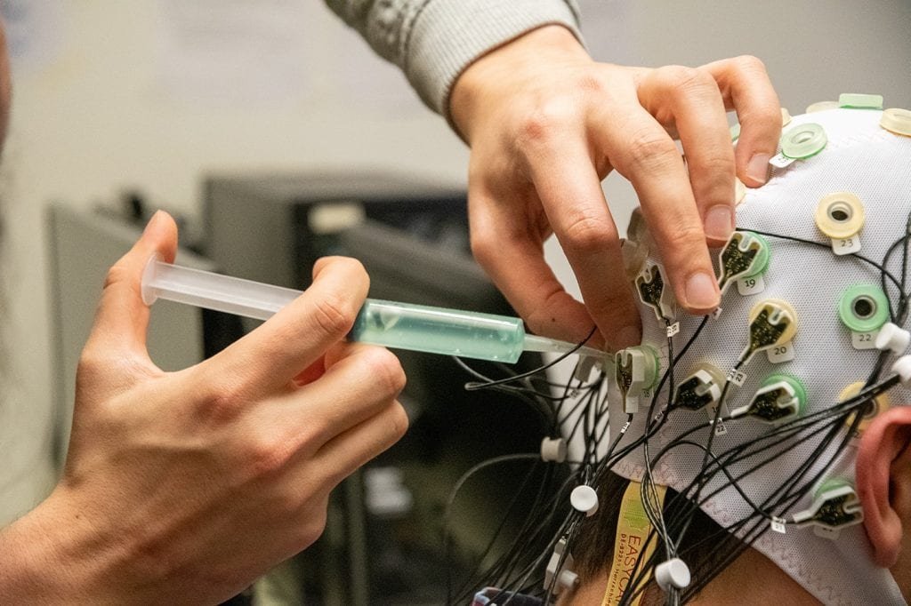
- ☐ Electrode gel and a blunt syringe for applying it
Power up and connect the hardware
Charge the battery, plug in the dongle, then switch on the board, always in that order.
- Charge the battery. Plug the battery’s white plug into the black USB charger, then plug the charger into a USB port. It is full when the charger’s light turns green.
- Plug in the dongle, facing upwards. A blue light should stay on and a red light should blink. Check that its switch is on GPIO6, the position closer to the computer, not RESET.
- Connect the battery to the Cyton.
- Switch the Cyton to PC. The switch on the board’s edge has three positions: BLE, OFF and PC. A blue light should come on. If it does not, press the RST button next to the switch, then check the battery is charged.
If the data ever looks broken later, unplug the dongle and switch the board OFF. Then plug the dongle back in first and switch the board on second.
Battery safety: only use the battery that came with the kit. Too much voltage damages the board. If anyone uses a different battery holder, check that red is + and black is − first; reversed wires burn out the board.
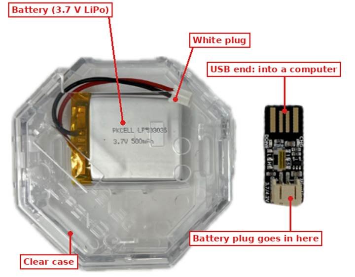
The battery, case and charger. To charge, push the battery’s white plug into the socket on the charger, then plug the charger’s USB end into a computer. The battery is full when the charger’s light turns green.
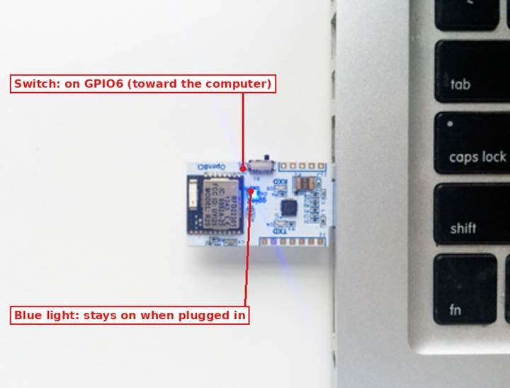
The dongle plugged into a laptop. The switch is set toward the computer (GPIO6), and the blue light stays on once it has power.
Understanding the pins
For EEG with a cap, you only use the bottom row of pins on each board. Both the Cyton and the Daisy have a strip of metal pins along one edge, arranged in two rows, a top row and a bottom row. Each pin is labelled in tiny print on the board.
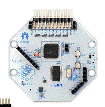
The Cyton board. The pin strip runs along the top edge; the cap cables connect to its bottom row.
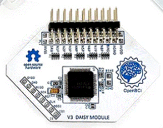
The Daisy module. It stacks on top of the Cyton and has its own pin strip along the top edge; its bottom-row pins carry channels 9–16.
On the bottom row, the pins that matter are:
- N1P to N8P: the eight recording pins. Each one becomes a channel in the GUI.
- SRB: the reference pin.
- BIAS: the ground-driving pin. Only the Cyton’s BIAS is used.
Leave the top row empty. It is used for other kinds of recordings, not standard cap EEG. Never connect anything to the power pins at the ends of the strip.
Tip: use a phone torch and your camera’s zoom to read the labels before you start.
Step 1: Connect the ground (BIAS to GND)
Connect the Cyton’s bottom BIAS pin to the cap’s GND location with one HPTA cable.
- Find the bottom BIAS pin on the Cyton (not the Daisy).
- Slide the board end of an HPTA cable onto that pin until it sits snugly.
- Plug the other end into the cap’s GND lead.
Why it matters: the ground removes noise the whole body picks up from the room, such as hum from lights and wiring. Without it, every channel is noisy.
Both boards have a BIAS pin: which one?
Use only the Cyton’s BIAS pin, even when you record from Daisy channels too. Leave the Daisy’s BIAS pin empty.
- The ground is for the person, not for each board. One connection grounds the person wearing the cap, and the Daisy’s channels benefit because they record from that same grounded person.
- Two ground connections can add noise. Connecting both BIAS pins can create an extra loop for electrical hum to travel around.
The reference works the opposite way. Every channel must compare its signal against REF, so both boards’ SRB pins are connected (Step 2).
| Pin | Cyton | Daisy |
| BIAS | Connect to cap GND | Leave empty |
| SRB (bottom row) | Connect via Y-splitter | Connect via Y-splitter |
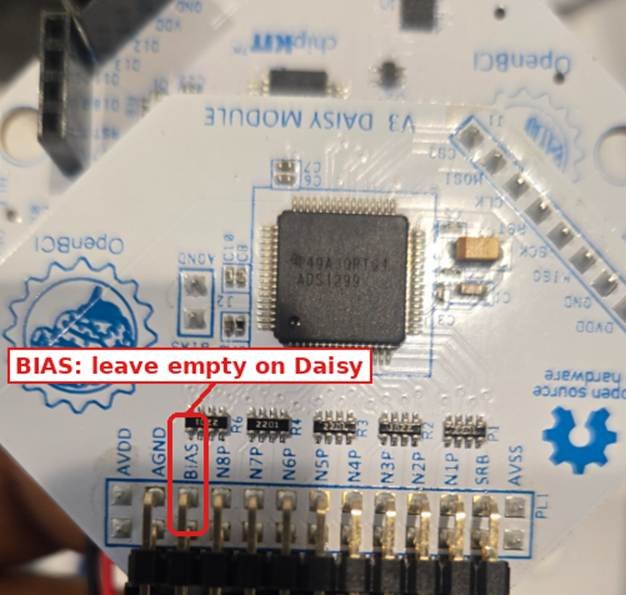
The Daisy’s pin strip, with BIAS circled in red. Leave this pin empty; only the Cyton’s BIAS connects to the cap’s GND. The labels above the pins read, left to right: AVDD, AGND, BIAS, N8P to N1P, SRB, AVSS.
Step 2: Connect the reference (SRB to REF)
Join the bottom SRB pins of both boards with the Y-splitter, then connect the Y-splitter’s single end to the cap’s REF location with an HPTA cable.
- Find the bottom SRB pin on the Cyton and the bottom SRB pin on the Daisy.
- Slide one branch of the Y-splitter’s split end onto each of those two pins. The two boards now share one reference. This is what “ganged together” means.
- Connect the Y-splitter’s single end to an HPTA cable.
- Plug the HPTA cable into the cap’s REF lead.
Why it matters: every channel on both boards is measured against REF. If REF is loose or has no gel, every channel goes wrong at once. When all channels misbehave together, check this connection first.
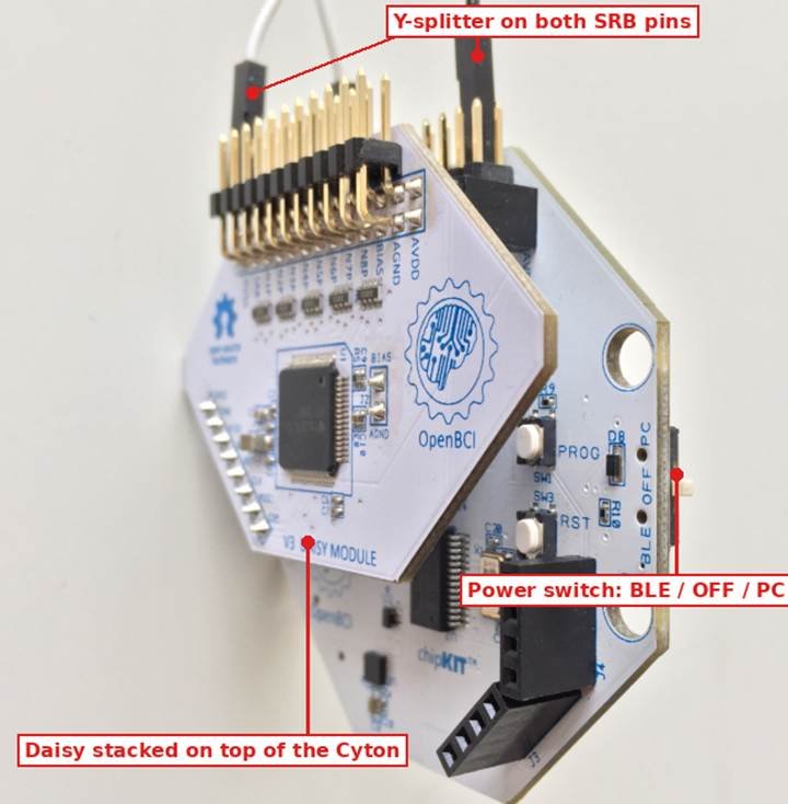
What Step 2 looks like when done. The Daisy sits stacked on top of the Cyton, and the Y-splitter’s two white wires go to the SRB pin on each board. The power switch on the Cyton’s edge has three positions: BLE, OFF and PC. Keep it on OFF while connecting cables, and use PC to stream to the dongle.
Step 3: Connect the recording electrodes
Every other cap electrode can go to any bottom recording pin, N1P to N8P, on either board, and the pin you choose decides its channel number in the GUI. GND and REF are the only exceptions; they always go where Steps 1 and 2 say.
The rule is simple:
| Board | Bottom pin | GUI channel |
| Cyton | N1P | 1 |
| Cyton | N2P | 2 |
| Cyton | N3P | 3 |
| Cyton | N4P | 4 |
| Cyton | N5P | 5 |
| Cyton | N6P | 6 |
| Cyton | N7P | 7 |
| Cyton | N8P | 8 |
| Daisy | N1P | 9 |
| Daisy | N2P | 10 |
| Daisy | N3P | 11 |
| Daisy | N4P | 12 |
| Daisy | N5P | 13 |
| Daisy | N6P | 14 |
| Daisy | N7P | 15 |
| Daisy | N8P | 16 |
In short: on the Daisy, add 8 to the pin number.
Two examples using the cap’s Fp1 electrode:
- Fp1 to the Cyton’s N1P shows up as channel 1.
- Fp1 to the Daisy’s N1P shows up as channel 9.
For each electrode, slide an HPTA cable onto the chosen pin and plug the other end into that electrode’s lead on the cap.
Tip: silver latch facing up. When you slide an HPTA cable’s connector onto a pin, turn it so the side with the small silver latch faces up. That side is slightly wider, so the connector sits better.
[Image needed: close-up of an HPTA connector with the silver latch visible]
Step 4: Plan and record your channel map
Decide which electrode goes to which pin before plugging anything in, and write it down. Without a written map, it is easy to forget which line in the GUI belongs to which spot on the head.
Tips:
- If you use 8 electrodes or fewer, put them all on the Cyton (channels 1–8). The numbers are easier to remember.
- Keep left-side electrodes (odd numbers, such as Fp1, F7) and right-side electrodes (even numbers, such as Fp2, F8) in a sensible order.
- Put a small label on each HPTA cable naming its electrode.
Example map for a forehead-only demo with an optional back-of-head pair:
| Cap electrode | Board | Pin | GUI channel | Used for |
| GND | Cyton | BIAS | none | Ground |
| REF | Cyton + Daisy | SRB, via Y-splitter | none | Reference |
| Fp1 | Cyton | N1P | 1 | Blinks, eyebrow raises |
| Fp2 | Cyton | N2P | 2 | Blinks, eyebrow raises |
| F7 | Cyton | N3P | 3 | Eye movements, jaw clench |
| F8 | Cyton | N4P | 4 | Eye movements, jaw clench |
| O1 (optional) | Cyton | N5P | 5 | Eyes-closed alpha rhythm |
| O2 (optional) | Cyton | N6P | 6 | Eyes-closed alpha rhythm |
Step 5: Match the settings in the OpenBCI GUI
The software must agree with your wiring: SRB2 and Bias on for every channel you use, and unused channels off.
- Open the OpenBCI GUI. In the System Control Panel, choose LIVE (from Cyton), then Serial (from Dongle).
- Pick the dongle’s port. On Windows it is named COM plus a number; on a Mac it starts with /dev/tty. It is usually at the top of the list. If it is missing, check the dongle is on GPIO6 and click Refresh List.
- Set the channel count to 16. It starts at 8. With the Daisy attached, you must click 16 CHANNELS, or channels 9–16 will not appear.
- Click START SYSTEM and wait about 5 seconds while it connects.
- In the Time Series panel, click Hardware Settings.
- For each channel in your map, make sure SRB2 is on. This tells the channel to use the REF connection from Step 2.
- Make sure Bias is included for those channels. This links them to the ground from Step 1.
- Turn off every channel you are not using. Click its numbered circle, or use Hardware Settings. This removes the clutter of empty channels.
- Click Filters and set the notch filter to 60 Hz (North America; use 50 Hz in Europe, Africa and most of Asia).

The first two choices in the System Control Panel. Left: under Data Source, choose LIVE (from Cyton). Right: under Pick Transfer Protocol, choose Serial (from Dongle).
[Image needed: the next screen, showing the port selected and 16 CHANNELS, just before START SYSTEM]
Quick check: the finger test
Before anyone puts on the cap, confirm the board and the GUI are talking to each other.
- Click Start Data Stream.
- Run a finger along the board’s pins.
- Every channel in the Time Series should jump wildly, and the lines in the FFT plot should shoot upwards.
If that happens, the connection works and any later problems are about the cap, gel or cables. If nothing changes, go back to “Power up and connect the hardware”.
[Image needed: Time Series screenshot during the finger test, with the channels jumping]
Checking it works and fixing common problems
A working channel shows calm, small wiggles in the Time Series, a Not Railed label, and roughly 5–50 µVrms. For a quick test, ask the wearer to blink: Fp1 and Fp2 (channels 1 and 2 in the example map) should show a clear spike each time.
| What you see | Most likely cause | What to do |
| Every channel railed or noisy at once | REF or GND loose, or no gel there | Check Steps 1 and 2, and add gel at REF and GND |
| One channel railed or noisy | That electrode has poor contact | Add gel through its hole, and check its HPTA cable is pushed fully on |
| A channel is flat at 0.00 µVrms | Nothing connected to that pin | Check the cable, or turn the channel off if unused |
| Signal appears on the wrong channel | Cable on a different pin than planned | Compare the board with your written map |
| Channels 9–16 missing | Channel count left at 8 | Restart the system with 16 CHANNELS selected |
| Constant hum, and the FFT shows a spike at 60 Hz | Notch filter set wrong | Set the notch to 60 Hz in Filters |
| GUI will not connect | Wrong port, board off, or dongle switch on RESET | Check the port and switches. Then unplug the dongle, switch the board OFF, plug the dongle in first and switch the board on. Still failing: restart the GUI |
| No radio channel number shown | Dongle and board not paired | In the System Control Panel, open Radio Configuration and click AUTOSCAN |
| Data looks choppy, arriving in bursts about once a second | Computer driver setting (FTDI latency) | Follow OpenBCI’s FTDI Driver Fix guide for Windows or Mac |
Give freshly gelled electrodes a minute to settle before judging them.
Where your recordings go: the GUI saves every session automatically in Documents → OpenBCI_GUI on the computer, named with the date and time.
Quick reference
- Power-up order: dongle in first (switch on GPIO6), then Cyton switched to PC.
- Ground: Cyton bottom BIAS → HPTA cable → cap GND.
- Reference: Cyton bottom SRB + Daisy bottom SRB → Y-splitter split end; single end → HPTA cable → cap REF.
- Recording electrodes: any cap electrode → HPTA cable → any bottom N1P–N8P pin.
- Channel numbers: Cyton N1P–N8P = channels 1–8; Daisy N1P–N8P = channels 9–16.
- Software: 16 channels selected, SRB2 on and Bias included for used channels, unused channels off, notch at 60 Hz.
- If everything is noisy, check REF and GND first.